

BOE DV212FBB-N10 TFT-LCD Panel Product Introduction
GENERAL DESCRIPTION
- Introduction
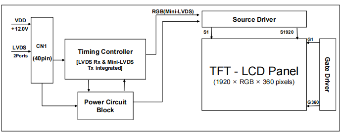
BOE DV212FBB-N10 is a color active matrix TFT LCD Open Cell using amorphous silicon TFT’s (Thin Film Transistors) as an active switching device. This Open Cell has a 21.2 inch diagonally measured active area with FHD resolutions (1920 horizontal by 360 vertical pixel array). Each pixel is divided into RED, GREEN, BLUE dots which are arranged in vertical stripe and this module can display 16.7M colors. The TFT-LCD Open Cell panel is adapted for a low reflection and higher color type.
Features
- LVDS interface with 2 pixel /clock
- High-speed response
- Low color shift image quality
- 8-bit color depth, display 16.7Mcolors
- Wide viewing angle
- DE (Data Enable) only mode
- HADS technology is applied for high display quality
- RoHS compliant
Application
- Home Alone Multimedia TFT-LCDTV
- Display Terminals for ControlSystem
- Full High Definition TV (FHD TV)
- AV application Products
General Specification
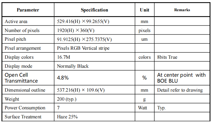
< Table 1. General Specifications >
ABSOLUTE MAXIMUM RATINGS
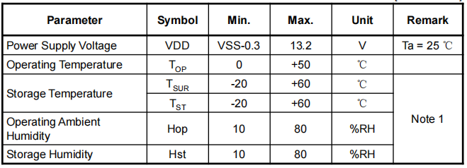
The followings are maximum values which, if exceed, may cause faulty operation or damage to the unit. The operational and non-operational maximum voltage and current values are listed in Table 2.
< Table 2. Open Cell Electrical Specifications >
[VSS=GND=0V]
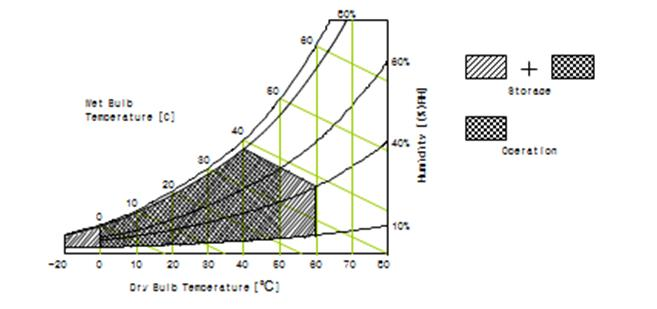
Note 1: Temperature and relative humidity range are shown in the figure below.
The wet-bulb temperature should be 39 ℃ max. and no condensation of water.
ELECTRICAL SPECIFICATIONS
- TFT LCD OpenCell
< Table 3. Open Cell Electrical Specifications >
[Ta =25±2 ℃]
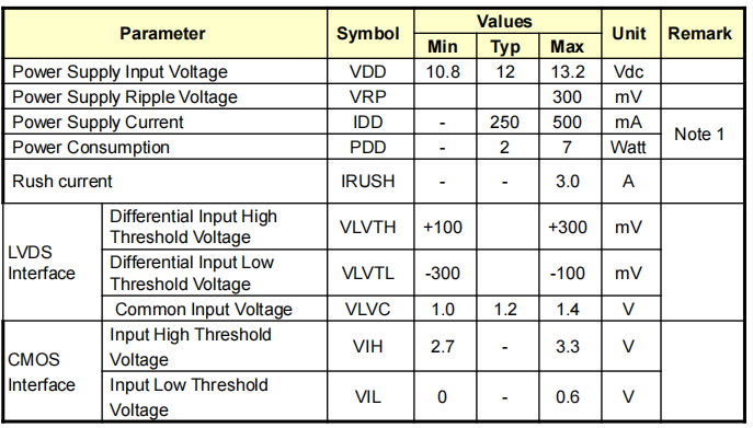
Note 1 : The supply voltage is measured and specified at the interface connector of LCM. The current draw and power consumption specified is for VDD=12.0V,
Frame rate fV=60Hz and Clock frequency = 74.25MHz.
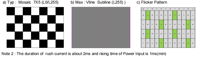
Test Pattern of power supply current
INTERFACE CONNECTION
Open Cell Input Signal & Power
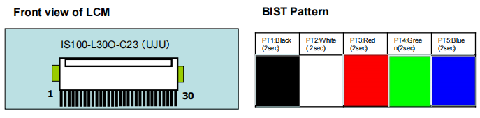
– LVDS Connector: IS100-L30O-C23 (UJU).
< Table 4. Open Cell Input Connector Pin Configuration >
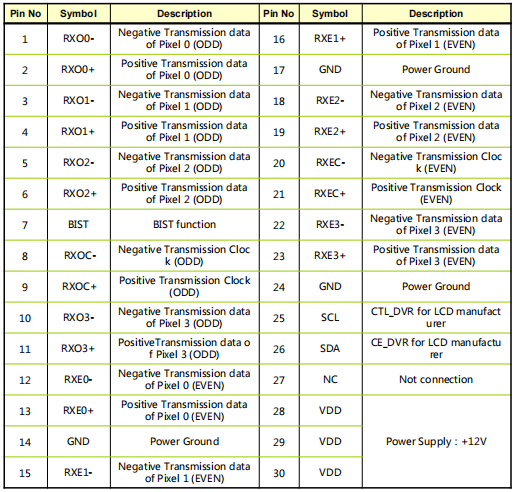
Notes: 1. NC(Not Connected): These pins are only used for BOE internal operations.
- Input Level of LVDS signal is based on the EIA-644 Standard.
LVDS Interface
– LVDS Receiver: Timing Controller (LVDS Rx merged) / LVDS Data: Pixel Data
OPTICAL SPECIFICATIONS
The test of optical specifications shall be measured in a dark room (ambient luminance1 lux
and temperature=252℃) with the equipment of Luminance meter system (Goniometer
system and PR730) and test unit shall be located at an approximate distance 180cm from
the LCD surface at a viewing angle of θ and Φ equal to 0. We refer to θØ=0 (=θ3 ) as the 3
o’clock direction (the “right”), θØ=90 (= θ12 ) as the 12 o’clock direction (“upward”), θØ=180 (= θ9
) as the 9 o’clock direction (“left”) and θØ=270(= θ6 ) as the 6 o’clock direction (“bottom”). While
scanning θ and/or Ø, the center of the measuring spot on the Display surface shall stay
fixed. The measurement shall be executed after 30 minutes warm-up period. VDD shall be
12.0V at 25C. Optimum viewing angle direction is 6 ’clock.
Note :
- Viewing angle is the angle at which the contrast ratio is greater than 10. The viewing are
determined for the horizontal or 3, 9 o’clock direction and the vertical or 6, 12 o’clock
direction with respect to the optical axis which is normal to the LCD surface.
- Contrast measurements shall be made at viewing angle of = 0 and at the center of the LCD
surface. Luminance shall be measured with all pixels in the view field set first to white, then
to the dark (black) state. (See Figure 1 shown in Appendix) Luminance Contrast Ratio (CR)
is defined mathematically.
Luminance when displaying a white raster
Luminance when displaying a black raster
- The color chromaticity coordinates specified in Table 9.shall be calculated from the spectral
data measured with all pixels first in red, green, blue and white. Measurements shall be
made at the center of the panel. The BLU is used by BOE.
- Response time Tg is the average time required for display transition by switching the input
signal as below table and is based on Frame rate fV =60Hz to optimize.
Each time in the below table is defined as Figure 2 and shall be measured by switching the
MECHANICAL CHARACTERISTICS
Dimensional Requirements
Figure 3(located in Appendix) shows mechanical outlines for the model DV212FBB-N10.
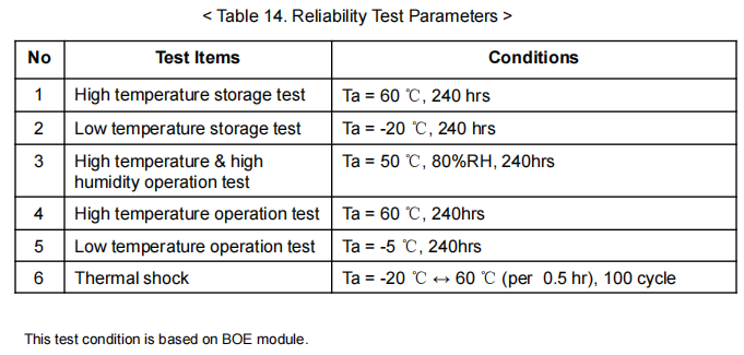
RELIABILITY TEST
The Reliability test items and its conditions are shown below.


Thanks for your knowledge sharing!